The deformation under load and the load distribution within the bearing are of great significance for the design of large rolling bearings such as rotor blade bearings. FE models are indispensable when it comes to determining the load distribution and also the stress distribution within the bearing. The available literature describes various approaches for modeling rolling bearings – some of which model the rolling elements with three-dimensional elements and others which replace them with spring elements. All these methods have a particular challenge in common: the validation of the models.
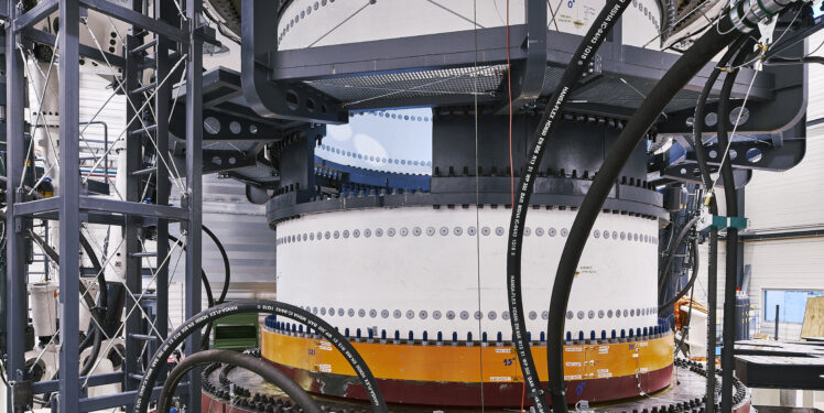
Since the completion of the Large Bearing Laboratory (LBL) in Hamburg, the IWES has developed a unique infrastructure for the testing of rolling bearings there in the scope of a range of different, funded projects (HAPT, HBDV; iBAC), and there will soon be a total of six test benches on which bearings of all shapes and sizes can be tested for failure mechanisms. The tests range from scaled foundation tests right up to accelerated long-term tests on real-scale rotor blade bearings. A realistic stiffness of the adapters is of great importance for the realistic testing of true-to-scale blade bearings on our BEAT6.1 test bench in particular. The design of these adapter components is the first step on the road to testing large rolling bearings and is performed with the help of FE simulations. For this purpose, FE models of both the bearing and the entire test bench were created in order to investigate the load and stress distributions within the bearing and within the adapter components.
Not nearly enough experimental data for possible validation have been published to date for large rolling bearings with diameters of between one and six meters in particular. As bearing dimensions increase, the diameters are becoming disproportionately larger than the ring cross sections, with the result that bearings of different sizes exhibit different structural stiffnesses. This phenomenon renders validation on a small scale followed by transposition of the modeling method to larger bearings difficult.
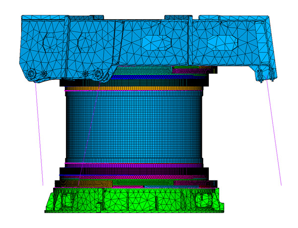
In order to nevertheless validate our FE bearing models, we have recreated our BEAT6.1 test bench virtually as an FE model. The realistic consideration of the structural properties and the characteristic, modular design of the test bench are particularly important for this, which is why each component was created separately and then all the parts joined together to form a complete model. These components are connected in the model via the modeling of bolts: each bolt is accounted for by its own beam element and connected to nodes of the surrounding structure via constraint equations. It is additionally possible to assign a corresponding coefficient of friction to the contact surfaces between the components. The hydraulic cylinders are modeled with linear actuators for introduction of the load. The forces actually acting on the test bench can then be taken from our database and assigned to the actuators as input parameters.
The test bench simulation is performed in two load steps: the first load step consists of applying the gravitational acceleration and “tightening” the bolts to their required preload force. In the second step, the modeled cylinders are then assigned their respective force. This allows the virtual test bench to be placed in a static loading condition identical to that of the actual test bench. Different measurement data are used to compare the model with reality and thus validate the bearing behavior. On the one hand, the stroke of the hydraulic cylinders can be compared with the deformed position in the model so as to investigate the general behavior of the test bench model, and, on the other hand, strain gauges are attached to both the real bearing and the bearing model. The comparison of the strain gauges can then be used to compare the deformation behavior of the bearings. Laser sensors are also attached, which measure the ring tilt of the test bearings at defined points. These can then be compared with the deformations of individual nodes from the model. This allows the influence of the bearing on the deformation of the overall model to be investigated via the stroke of the cylinders and the bearing model itself to be validated via the tilt of the bearing rings.
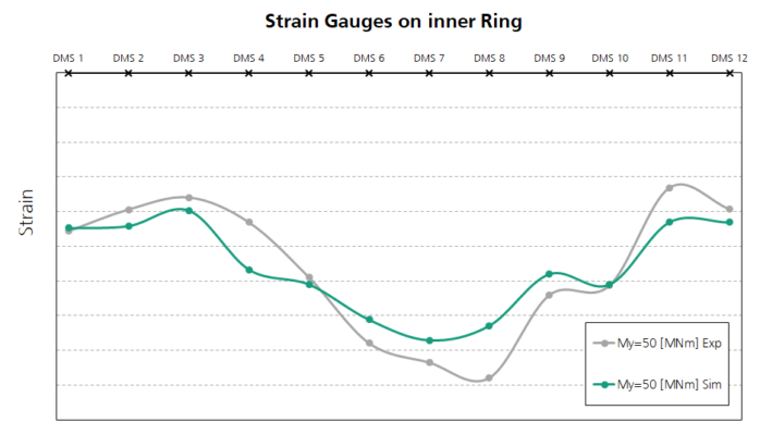
Diagram 1 shows an example of the comparison of the strain gauges for an experimental test with the corresponding data from the simulation. Here, a total of 12 strain gauges were attached to the bearing inner ring at 30 degree intervals around the circumference. It can be clearly seen that the qualitative progression of both curves is very similar.
The successful validation of this FE test bench model offers considerable advantages: for one thing, the adapter components can be designed more reliably, ensuring realistic loading of the blade bearing during accelerated long-term operation, and, for another, the data collected during the test provide a unique opportunity for validation of the FE bearing models.
The further development of the virtual test bench at the IWES can be divided into two time horizons:
in the short term, the test bench model will enable the further development and validation of modeling methods for large rolling bearings, and, in the medium to long term, in addition to mapping the test environment and a numerical test design, it should also be possible to test the bearing virtually to the extent that a reliable service life calculation is possible.
More information here: