Part 3: Rapid testing of blade bearings – The first endurance run.
In Part 1, I introduced the idea of an accelerated endurance run for blade bearings, which would consist of all wear-inducing cycles in direct succession. In Part 2, I described how experimental results debunked this idea and gave rise to the concept of protection runs. In the third and final part, I will provide some insights into how we were able to verify this concept.
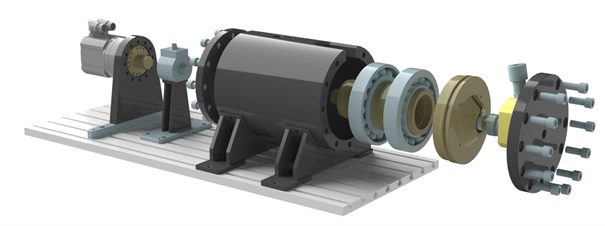
The tests on the BEAT2.1 resulted in the idea of protection runs, but there was no research available from any other institution that already confirmed this concept. Most test rigs for oscillating operation were not capable of varying amplitudes. It became apparent that we needed to confirm the test results at the IWES. However, the BEAT2.1 was not the right tool for this job due to its high operating costs and the limitations on publishing the results. Scaled tests with much smaller bearings seemed a good idea, because they are lower cost, faster, and all details can be published. This idea developed into the BEAT0.1 test rig: a rig for angular contact ball bearings with an outer diameter of 180 mm. It was designed to apply a static axial load and have a drive that can reproduce any time series.
It was at that time, in spring 2018, that our small research team moved into the new Hamburg facilities: the Large Bearing Laboratory, or LBL for short, and I was able to start to run the first tests with the BEAT0.1 by the end of the year. The first lesson we learned was that oscillating operation with frequent stops and starts is a challenge for a drive. Our motor had a rated torque of 50 Nm, which was about 2.5 times the test peak torques. However, owing to the high frequencies of the stops and starts, it began to overheat very quickly. The first solution was to introduce short breaks between the cycles, later on a PC cooling fan in a 3D-printed housing solved the issue completely.
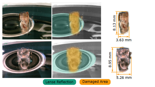
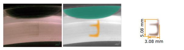
I presented the first results of these tests at the inauguration of the LBL in May 2019. Previous work by my colleague Fabian Schwack at the Institute of Machine Design and Tribology (IMKT) had already indicated that it was possible to scale wear tests for the purpose of a general understanding of damage modes. I was able to confirm this and show a similarity between the damage modes in full-scale blade bearings and type 7220 bearings. We carried out 40,000 cycles with the BEAT2.1 and employed the same number for the first series of tests with the BEAT0.1. The tests confirmed the results of the BEAT2.1 and thereby the concept of protection runs.
With the commissioning of the BEAT6.1, we were able to cross-reference these tests with the 5 m diameter blade bearings and achieved similar results. These then allowed us to set up the final wear endurance run program for the large bearings. In a nutshell, the program takes everything detrimental (constant small amplitudes) and everything beneficial (any movement that spans more than 15°) from the operational time of the turbine and combines these sequences into one time series. The details of this are part of my PhD thesis. In our research, the source data are the aero-elastic simulation data time series of the IWES reference turbine IWT-7.5-164 with an Enercon controller (download time series here). This program turned 20 years of operation into just 117.1 days of test time. We executed the program on two 5 m diameter, four-point contact ball bearings in 2019.
In these blog articles, I have demonstrated the development and explained individual steps on our way towards a successful concept for accelerated tests of rotor blade bearings. The IWES team started with a blank drawing board, tackled various challenges, raised scientific questions, and ended by executing the final program – and thus established a new way of testing blade bearings.
More information here:
Part 2: Rapid testing of blade bearings – from the desk to the test bench